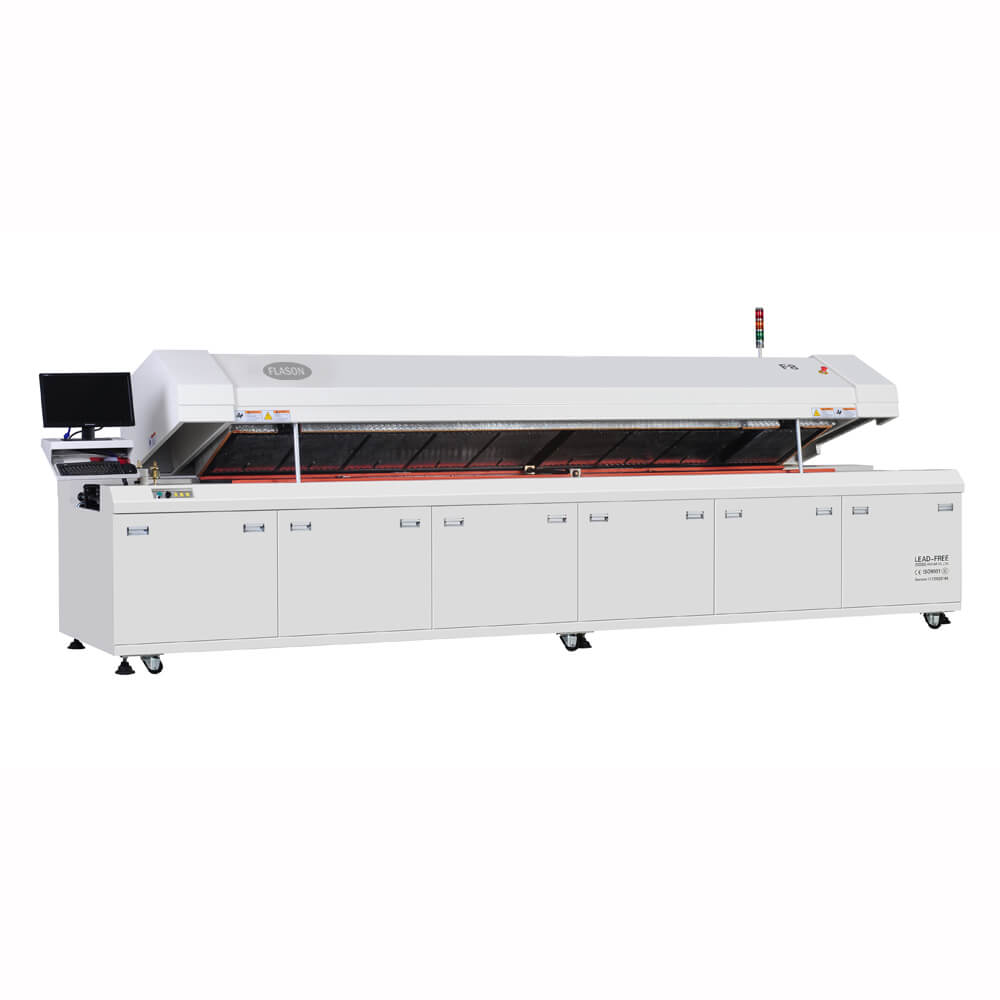


The pick and place machine places the SMD components onto the board, and they are held in place by the surface tension of the solder paste. Then with all the components in place they can be moved to the reflow soldering oven. It is possible for the components to be glued to the board, but this makes rework very difficult. This is quite sufficient for normal handling, although some care is obviously needed.

PCB REFLOW OVEN MANUAL
Normally, an automatic pick and place machine is used because the numbers of components used nowadays, the accuracy and turnaround required make manual placement non-viable. Pick and Place: With the solder paste on the board, the components can then be set in place.Once printed, the solder paste has been added to the board, it can move on to the next stage through SMT line rail. This only allows the solder paste to be added to those areas of the board where it is needed. This is achieved by having a solder paste printer. While boards have solder resist ( solder mask) layers added to them, it is necessary to only add solder paste to those areas where the solder is actually required. The paste is only deposited to the contact pads that require soldering. Solder Paste: In essence solder paste is applied to the board.The first stage in reflow soldering for SMT assembly is to apply solder paste and place components to the printed circuit boards, which can be flex, rigid, metal core and rigid-flex. In SMT house, the heating can be accomplished by passing the assembly through a reflow oven by soldering individual joints. The solder paste reflows in a molten state, creating permanent solder joints. I'll have to read chinglish manual and see if I can create my own profiles it looks like these boards need less preheating and a faster rise to reflow temperature as there is less material to preheat.Infra-Red (IR) Reflow Soldering is a SMT process in PCB assembly manufacturing, in which a solder paste is used to temporarily attach one or thousands of tiny SMD components to their contact pads on bare printed circuit board, after which the entire SMT assembly is subjected to controlled heat. With the copper actually reflect the heat from the infrared bulbs? Even on the bottom of the board I can see that the bottom has heated up around small copper plane but under the copper plane the board looks fine. I think I will add some ground planes to help distribute the heat. This is however my 1st attempt with 0.8 mm boards. The boards came from PCB cart I've had a few deliveries from them and generally not had a problem. So the only way of getting proper heat onto the board is to put them down the middle where they are going to get the maximum temperatures anyway. This is a very small oven I have previously tried to do 9 of my 2 in.² boards all at once but this meant that I had 3 boards in between the 2 heating elements and then to lots of 3 boards either side of one heating element and the boards that were on the 2 outer rows did not properly reflow. I'm not sure how it would help me though. I do in fact have a thermal imaging camera.

I see when in fact the small amount of copper plane I am using as heat sinks and for LEDs does seem pretty much untouched. Time perhaps for a new controller for it? So has this been caused by the thinner board which I did in the hope of saving material yes I am an environmentalist but also saving weight for when these things are shipped in volume from China or was this caused by the lack of copper pours all over the board? Does the copper covering do something to protect the a FR4 from the infrared heat? Do I simply need to use a different reflow profile? I'm not sure that these ovens actually allow me to create my own profile. After the 1st one went up in smoke I tried another one and observed it and as soon as I saw the PCB start to bubble I pulled the tray open and it was saved and the parts were perfectly re-flowed. The overheating of the board is starting just as the parts reflow. The main difference from the original design is that the board is now 0.8 mm thick but I have also not put any filled planes on it. I have just had the same board made and I offered it and things got a bit smoky as the FR4 started to delaminate and smoulder. I also successfully assembled a board that boards about 100 x 90 mm and 1.6 mm thick. I have used it to produce a number of boards now mostly all of them to inches by 2 inches and 1.6 mm thick. I have one of those cheap reflow oven's from China the T962.


 0 kommentar(er)
